Why Are Mold Parts Important for Product Quality?
Mold Parts are easy to overlook when a finished product looks polished. Yet a small mismatch in a cavity, core, or ejector pin can leave flash, sink marks, or uneven dimensions. The result may be a part that looks acceptable but fits poorly during assembly. Small errors matter.
John Beaumont, an injection-molding specialist and author of The Moldflow Design Guide, has written extensively about how mold design and processing affect part quality. A practical paraphrase of his guidance is: “Consistent parts depend on a mold and process designed to work together.” This is a summary, not a verbatim quotation.
That relationship starts with details. Steel selection affects wear and heat transfer. Gate location influences filling and visible marks. Cooling channels help control shrinkage, while accurate alignment supports repeatable dimensions. These choices shape surface finish, strength, cycle time, and production consistency. They also affect maintenance needs over the mold’s service life.
Good Mold Parts do not guarantee perfect products. Material variation, machine settings, and inspection methods still matter. This is where I would pause before making broad claims: a well-built mold cannot fix every process problem. Manufacturers should validate designs with suitable testing, dimensional checks, and trial runs. Careful review turns small design decisions into measurable quality gains.
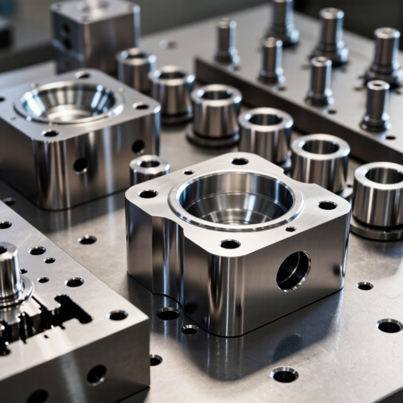
What Mold Parts Are and How They Function
Mold parts are the precision components that shape and control a molded product. The cavity forms the outer surface; the core creates internal features such as holes or ribs. Their fit determines whether those features land in the right place. Small, but critical.
Runner channels carry molten material toward the gate, which controls how it enters the cavity. Cooling channels remove heat through the mold, while vents let trapped air escape. Ejector pins then push the cooled part free. If a vent is blocked, burn marks or incomplete filling may appear. If cooling is uneven, a part can warp after ejection. Each component has a specific job, but their effects overlap.
ISO 20457:2018 groups tolerances for molded plastic parts into nine tolerance groups, TG1 to TG9. It does not set one universal tolerance for every part; material, dimensions, and production conditions matter. That is useful context when choosing mold clearances or inspecting parts. In practice, a clean mold can still produce inconsistent results if cooling or filling is poorly balanced. The awkward truth: a mold may look precise and still need adjustment after trial shots. Engineers check dimensions, surface finish, and ejection marks together, because one measurement rarely tells the whole story.
Which Components Shape and Release the Product
The cavity and core are the mold surfaces that give a product its basic shape. One forms the exterior; the other shapes internal features, such as ribs, holes, and snap-fit details. Their alignment matters. A small mismatch can leave a visible seam or an uneven edge. Not every mark is a defect, but it should be understood before production.
Other components handle details and release. Slides and lifters move aside to clear undercuts that would otherwise trap the part. Ejector pins then push the cooled piece from the cavity. Their positions need care: a pin can leave a small witness mark, especially on a smooth or visible surface. It sounds simple. It isn’t.
Gates and runners guide molten material into the cavity, while vents let trapped air escape. Cooling channels help control temperature and cycle time. Uneven cooling can cause warping or sink marks, even when the mold looks well made. In practice, part geometry, material, and process settings all affect results. A mold designer should review likely release points and test parts under realistic conditions. I would not assume one trial proves the design; production can reveal issues that a short test misses.
How Mold Part Design Affects Dimensions and Surface Finish
Why Are Mold Parts Important for Product Quality?
How Mold Part Design Affects Dimensions and Surface Finish
Mold design determines how plastic flows, cools, and releases. A thin rib beside a thick wall can cool unevenly, causing sink marks or warped edges. Gate position, vent depth, and cooling-channel spacing also affect repeatability. Even a polished cavity cannot compensate for poor flow or trapped air. Small errors grow.
ISO 20457:2018 provides tolerance classes and dimensional tables for plastic moulded parts; it does not set one universal tolerance for every resin and geometry. Designers should use the relevant class as a starting point, then validate dimensions with trial parts and production measurements. Surface finish needs the same care. ASME B46.1-2019 defines roughness parameters such as Ra, but a low Ra value alone does not guarantee a defect-free visible surface. Texture, gloss, and resin choice matter too. A glossy panel can reveal a faint weld line that a textured surface hides.
Tips: Place gates away from prominent cosmetic areas, keep wall thickness as uniform as practical, and confirm critical dimensions after the part has cooled. Record cavity temperature and measurement conditions; otherwise, comparisons may mislead. These checks take time, and teams sometimes skip them. That is worth reconsidering before tooling is finalized.
How Materials and Fit Help Prevent Defects
Why Are Mold Parts Important for Product Quality?
How Materials and Fit Help Prevent Defects
Resin choice affects shrinkage, stiffness, and surface finish. The Society of Plastics Engineers’ Plastics Engineering Handbook gives typical molding shrinkage ranges of about 1.0–2.5% for polypropylene and 0.4–0.7% for ABS. Actual values vary by grade and process. That difference matters: a cavity sized for one resin may produce undersized clips or uneven seams with another. Material data should guide cavity dimensions before tooling is finalized.
Fit matters just as much. A small mismatch between mold halves can leave a visible flash line; uneven cooling can warp a flat panel or shift holes out of position. Check shutoff surfaces, alignment pins, and cavity wear, then measure trial parts at several points. It is tempting to blame the tool for every defect, but resin moisture, melt temperature, and packing pressure can also be responsible. The tool is not always the culprit.
Tips: Confirm the resin grade and its shrinkage data before cutting steel. Inspect molded parts under consistent lighting, and record dimensions after cooling. Small checks catch costly surprises.
Why Are Mold Parts Important for Product Quality?
How materials and fit help prevent defects
Typical linear thermal expansion coefficients vary by material. For the same temperature change, materials with higher coefficients expand more, which can affect clearances and alignment between mold parts. Choosing compatible materials and maintaining precise fit helps reduce dimensional mismatch, flash, and uneven wear. Values are approximate and vary by grade and temperature.
How Maintenance Supports Consistent Product Quality
How Maintenance Supports Consistent Product Quality
A clean, well-maintained mold helps keep dimensions, surface finish, and cycle times stable. After repeated production runs, residue can collect around vents and parting lines. Ejector pins may also wear or stick. Small defects compound. A faint flash today can become a recurring trim problem tomorrow.
Routine checks make these changes easier to catch. Technicians can inspect venting, cooling channels, alignment, and pin movement between runs, then record findings against shot counts. Cleaning should match the mold material and contamination; aggressive tools can damage delicate features. It is easy to rush an inspection when production is behind. That is a risk worth admitting, not hiding.
Deloitte’s 2017 predictive-maintenance analysis estimates potential maintenance-cost reductions of 25–30% and 70–75% fewer breakdowns. These are broad industrial estimates, not guarantees for mold shops. Still, they show why condition-based maintenance matters: fewer unexpected stops can mean fewer rushed restarts and less variation between batches. A maintenance log is useful, but only if someone reviews it and acts on repeated temperature shifts, rising cycle times, or recurring surface marks.