
7 Tips for Choosing a Hydraulic Piling Rig?

Choosing a Hydraulic Piling Rig is not just a matter of comparing engine power. The right machine must match the pile design, ground conditions, site access, and production schedule. A rig that performs well on open ground may struggle beside existing buildings or beneath overhead restrictions. Small details matter. Hose routing, mast clearance, and room to position support equipment can change the whole working day.

The scale of infrastructure demand makes careful equipment selection more than a purchasing detail. The Global Infrastructure Hub’s 2017 Global Infrastructure Outlook estimated that the world would need about $94 trillion in infrastructure investment by 2040, with a projected $15 trillion gap under then-current trends. That forecast is not a piling-equipment sales figure, but it highlights the pressure to deliver durable projects efficiently. Technical guidance from the Federal Highway Administration also stresses the importance of matching foundation methods to site conditions and construction requirements. In practice, that means reviewing more than brochure capacity. Compare pile type, installation force, hydraulic flow, carrier stability, transport limits, maintenance access, and operator support. Ask for performance evidence on ground similar to yours. Then check the assumptions behind it. A specification can look convincing and still leave unanswered questions. The seven tips below provide a practical framework for evaluating a Hydraulic Piling Rig, while recognizing that no single machine suits every site.
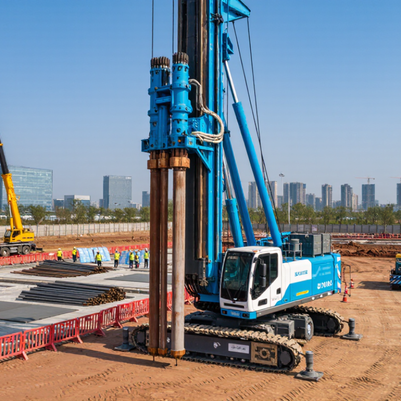
7 Tips for Choosing a Hydraulic Piling Rig?

Define the Pile Scope: Typical Diameters Range from 300 to 2,500 mm

Pile diameter is a practical starting point when selecting a hydraulic piling rig. Common project requirements may range from 300 to 2,500 mm, but that span is not a single machine setting. A rig suited to a 300 mm pile may lack the torque, clamp capacity, or working clearance needed for a much larger one.

Small piles still bite.

Record the full diameter range, not just the most common size. Then check pile material, wall thickness, length, and installation method. A 1,200 mm casing, for example, needs compatible clamps and enough leader clearance. Larger piles often require higher torque and crowd force, while long piles place extra demands on lifting and alignment. Check the rig’s performance charts against the actual soil conditions and planned tooling.

The stated diameter is only part of the scope. Ground conditions, obstructions, and pile tolerances can change equipment needs after work begins. That can be easy to overlook. Ask the design and site teams to confirm the largest and smallest piles, expected depth, and any casing changes before choosing a rig. A little uncertainty should stay visible in the plan; tidy specifications do not always match the ground.

Match Torque to Ground Conditions: Compare Rig Ratings in kN·m

A rig’s torque rating should match the ground profile, not just the pile diameter. Compare continuous operating torque in kN·m, not only the peak figure; a brief peak may not help when dense layers resist rotation. Peak torque can mislead. For a screw-pile site, review boreholes and soil logs for fill, clay, sand, and gravel before selecting a rig. Soil varies.

Tip: Use field data, not guesswork. ASTM D1586/D1586M describes the Standard Penetration Test: a 63.5 kg hammer drops 760 mm, and the recorded N-value counts blows for the final 300 mm of penetration. That result helps characterize soil resistance, but it does not convert directly into a rig’s required torque. ICC-ES AC358 evaluates helical pile systems using installation torque correlations; those factors are system-specific, not universal rig ratings.

Check torque at the working speed and depth you expect, then allow for harder layers and wear. Ask for torque-monitoring records from comparable ground, if available. I would not choose a rig from one headline number alone. A rig that stalls in gravel wastes time; excessive capacity can also mean unnecessary cost and machine weight. Match rated torque to site evidence, and verify it during installation.

Check Required Depth and Reach: Some Rigs Drill 20–60 m Piles

A quoted 20–60 m drilling capacity is a starting point, not a design promise. Check whether it means maximum drilling depth, usable pile length, or depth measured below the working platform. These are not interchangeable. The Federal Highway Administration’s 2010 Geotechnical Engineering Circular No. 10 reports drilled-shaft diameters commonly ranging from 0.6 to 3.0 m. That scale matters: a rig reaching 40 m with a narrow tool may not reach the same depth with a larger auger, casing, or unstable ground. Depth is not reach. Check mast clearance, leader angle, tool stroke, and space beneath nearby structures.

For a planned 35 m pile, compare the rig’s documented capacity with the actual bore diameter and soil profile. Ask how groundwater, loose layers, and temporary casing affect achievable depth. Confirm torque and crowd force for the chosen tooling, plus the rig’s ability to withdraw it from deep, sticky soil. A capacity chart alone can be an imperfect shortcut. Request project records or a test-bore plan for comparable ground, and have the geotechnical designer review the assumptions. Small details matter: a low overhead obstruction or a changing platform level can reduce usable reach, even when the brochure figure looks sufficient.

7 Tips for Choosing a Hydraulic Piling Rig: Check Required Depth and Reach

Tip What to Check Practical Guide Why It Matters
1. Match the rig to the required pile depth Confirm the design pile length and the rig’s usable drilling or installation depth with the selected tooling. Projects may require piles around 20–60 m deep. Treat this as a project range, not a guarantee of any one rig’s capacity. Actual achievable depth depends on the rig configuration, ground conditions, casing or drill-rod length, and installation method.
2. Check working height and reach Review leader or mast height, available overhead clearance, access width, and the rig’s permitted operating position. Compare the rig’s setup dimensions with site restrictions such as bridges, buildings, utilities, and low overhead lines. A rig may have sufficient depth capacity but still be unsuitable if it cannot be safely positioned or operated on site.
3. Select the right piling method Determine whether the design calls for driven piles, bored piles, continuous-flight auger piles, or another system. Match the rig and attachments to the specified method, pile material, and construction sequence. Different methods use different tools and produce different installation effects, noise levels, and spoil requirements.
4. Verify pile diameter and tooling compatibility Check the required pile diameter, auger or drill-bit size, casing needs, and connection compatibility. Use the equipment manufacturer’s configuration data for the intended diameter and depth combination. Maximum diameter and maximum depth are not always available together; soil resistance and tooling can limit performance.
5. Assess ground conditions Review the geotechnical report for soil layers, groundwater, cobbles, rock, and potential obstructions. Confirm whether the planned tools can handle the expected strata and whether casing or rock drilling tools are needed. Ground conditions affect penetration rate, stability, achievable depth, and the need for additional equipment.
6. Check lifting capacity and stability Review the rig’s load charts, operating weight, track width, ground-bearing pressure, and any lifting duties. Assess the actual working configuration and ground support; do not rely on rated capacity without checking the relevant radius and setup. Safe operation depends on both the rig’s capacity and the stability of the working platform.
7. Compare productivity, transport, and support Consider expected daily production, setup time, transport dimensions, maintenance access, and availability of service support. Compare the complete job plan, including mobilization, tooling changes, spoil handling, and inspection requirements. A suitable rig must meet the technical specification while fitting the project schedule, site logistics, and operating requirements.

Note: Confirm final rig selection against the project design, geotechnical conditions, site constraints, and the equipment supplier’s technical specifications.

Verify Hydraulic Compatibility: Match Flow in L/min and Pressure in MPa

Hydraulic compatibility starts with two numbers: flow in L/min and pressure in MPa. A piling rig may require a specific flow range to operate its rotary head or impact system properly. Too little flow can slow rotation and reduce production. Too much may cause overheating or unwanted movement. Pressure matters too; insufficient pressure can limit working force, while excessive pressure can damage components.

Compare the rig’s requirements with the carrier’s hydraulic output, not just the figures in a sales sheet. Check whether the stated flow is available at the required pressure and engine speed. A pump’s idle reading can be misleading. Measure under load. Also confirm return-line limits, hose size, and any case-drain requirements. These details are easy to overlook, yet a restricted return line can raise oil temperature quickly.

On site, watch the oil temperature during a realistic test cycle, especially when the rig works continuously. Warm oil may behave differently from cold oil, and an apparently close match can still prove unreliable. Small mismatch, big trouble. If specifications are unclear, ask a qualified technician to verify the circuit before connecting the rig. I would not rely on a quick visual check alone; it can miss pressure losses across long hoses and fittings.

Assess Stability and Transport: Compare Operating Weight and Ground Pressure

A piling rig’s operating weight is only useful when matched to its actual track footprint. Consider a hypothetical 40-tonne rig resting on 8 square metres of track area. Its average static pressure is about 49 kPa, using weight divided by contact area. A calculation, not a site rating. FHWA’s Soils and Foundations Reference Manual explains that bearing capacity depends on soil strength and loaded-area geometry. That matters on wet fill, loose sand, or a recently excavated platform. The same rig can be stable on compacted ground and unsafe a few metres away.

Check the manufacturer’s operating configuration, including mast, leads, and counterweights; transport weight alone can mislead. Ask for track dimensions and maximum ground pressure, then compare them with a geotechnical assessment of the working platform. FHWA guidance supports assessing soil conditions and equipment loads together, rather than relying on a single nominal pressure. Remember, the 49 kPa estimate excludes dynamic forces, uneven track contact, and load changes during rotation or pile driving. A soft patch under one track can matter more than the site-wide average. Walk the platform. Inspect drainage, edges, and recently placed fill. I would still question a neat number on a specification sheet if the ground beneath it has not been checked.

7 Tips for Choosing a Hydraulic Piling Rig: Assess Stability and Transport

Compare operating weight with nominal ground pressure. The points below are illustrative calculations—not specifications for particular rigs—using pressure = rig mass × 9.81 ÷ total track contact area.

Illustrative configurations assume total track contact areas of 4.8 m², 8.0 m², and 12.0 m². Actual ground pressure depends on the machine’s track dimensions, attachments, and working setup; confirm operating weight and ground-bearing requirements before transport or site preparation.